Chapter 1. Introduction

Each of the past three centuries has been dominated by a single technology. The 18th century was the era of the great mechanical systems accompanying the Industrial Revolution. The 19th century was the age of the steam engine. During the 20th century, the key technology was information gathering, processing, and distribution. Among other developments, we saw the installation of worldwide telephone networks, the invention of radio and television, the birth and unprecedented growth of the computer industry, and the launching of communication satellites.
As a result of rapid technological progress, these areas are rapidly converging and the differences between collecting, transporting, storing, and processing information are quickly disappearing. Organizations with hundreds of offices spread over a wide geographical area routinely expect to be able to examine the current status of even their most remote outpost at the push of a button. As our ability to gather, process, and distribute information grows, the demand for ever more sophisticated information processing grows even faster.
Although the computer industry is still young compared to other industries (e.g., automobiles and air transportation), computers have made spectacular progress in a short time. During the first two decades of their existence, computer systems were highly centralized, usually within a single large room. Not infrequently, this room had glass walls, through which visitors could gawk at the great electronic wonder inside. A medium-sized company or university might have had one or two computers, while large institutions had at most a few dozen. The idea that within twenty years equally powerful computers smaller than postage stamps would be mass produced by the millions was pure science fiction.
The merging of computers and communications has had a profound influence on the way computer systems are organized. The concept of the ''computer center'' as a room with a large computer to which users bring their work for processing is now totally obsolete. The old model of a single computer serving all of the organization's computational needs has been replaced by one in which a large number of separate but interconnected computers do the job. These systems are called computer networks. The design and organization of these networks are the subjects of this book.
Throughout the book we will use the term ''computer network'' to mean a collection of autonomous computers interconnected by a single technology. Two computers are said to be interconnected if they are able to exchange information. The connection need not be via a copper wire; fiber optics, microwaves, infrared, and communication satellites can also be used. Networks come in many sizes, shapes and forms, as we will see later. Although it may sound strange to some people, neither the Internet nor the World Wide Web is a computer network. By the end of this book, it should be clear why. The quick answer is: the Internet is not a single network but a network of networks and the Web is a distributed system that runs on top of the Internet.
There is considerable confusion in the literature between a computer network and a distributed system. The key distinction is that in a distributed system, a collection of independent computers appears to its users as a single coherent system. Usually, it has a single model or paradigm that it presents to the users. Often a layer of software on top of the operating system, called middleware, is responsible for implementing this model. A well-known example of a distributed system is the World Wide Web, in which everything looks like a document (Web page).
In a computer network, this coherence, model, and software are absent. Users are exposed to the actual machines, without any attempt by the system to make the machines look and act in a coherent way. If the machines have different hardware and different operating systems, that is fully visible to the users. If a user wants to run a program on a remote machine, he [![]() ] has to log onto that machine and run it there.
] has to log onto that machine and run it there.
[] ''He'' should be read as ''he or she'' throughout this book.
In effect, a distributed system is a software system built on top of a network. The software gives it a high degree of cohesiveness and transparency. Thus, the distinction between a network and a distributed system lies with the software (especially the operating system), rather than with the hardware.
Nevertheless, there is considerable overlap between the two subjects. For example, both distributed systems and computer networks need to move files around. The difference lies in who invokes the movement, the system or the user. Although this book primarily focuses on networks, many of the topics are also important in distributed systems. For more information about distributed systems, see (Tanenbaum and Van Steen, 2002).
The first linkage of computing and communication devices occured in 1940, when Dr. George Stibitz used telegraph lines to send data files from Dartmouth college in New Hampshire, USA to a Bell Laboratories calculator in New York city, USA.
.jpg)


 ·
·
Source: where the data is originated. Ex: computer, cell phone, etc
The first linkage of computing and communication devices occured in 1940, when Dr. George Stibitz used telegraph lines to send data files from Dartmouth college in New Hampshire, USA to a Bell Laboratories calculator in New York city, USA.
1.0 UNDERSTAND bASICS OF dATA COMMUNICATION.
1.1 define data communications.
1.2 need for data communication networking.
1.3 distinguish between analog and digital transmission.
1.4 explain serial and parallel communication.
1.5 define baud rate, simple, half duplex and full duplex communication.
1.6 define channel capacity.
1.7 list different transmission media.
1.8 explain the cross section and applications of twisted pair cable, UTP, STP, co-axial cable, optical fibre.
1.9 know about infrared and light wave transmission.
1.10 explain about data and signals (digital data digital signals, digital data analog signals, analog data digital 1.11 signals, analog data analog signals).
1.12 compare characteristics of transmission media.
1.13 explain shannon capacity.
A simple data communication model:


Source: where the data is originated. Ex: computer, cell phone, etc
·
Transmitter:
converts data into a suitable form for transmission through the medium
·
Communication
system: medium through which signal
is sent. Ex: piece of wire, optical fibre, LAN, WAN (INTERNET),MAN
·
Receiver:
which receives the signal and converts it into data or message
·
Destination:
where the data is sent
Source: is generating some data , here data means which
sends message, pic,jpeg,images,videos,programs
This data can be analog, digital. Data is transmitted
through electromagnetic signal, the signal may be electronic nature or optical
nature
w Analog
data
n Voice
n Images
w Digital
data
n Text
n Digitized
voice or images
1. What is data communication?
Ans: electronic transmission of information that has
been encoded digitally (as for storage and processing by computers) (or) I would define data communication as the transfer
of information between two points, either via an analogue (sine wave)
electrical signal. or digital (binary ) signal via electrical pulses or
optically via light pulses
2. What is computer network?
more than
one computer interconnected through a communication medium for information
interchange is called a computer network.
3. Need of Data communication and Networking?
ans:
3. Need of Data communication and Networking?
ans:
- Signal
generation
- Interfacing
- Synchronization
- Exchange
Management
- Transmission
System
- Error
Detection and Correction
- Flow
Control
- Addressing
- Routing
- Message
formatting
- Distributed
data base
- Cheap and
efficient data transmission over long distances
- Provides
robust communication infrastructure
- Enables
e-commerce, e-governance, e-services
Signal generation: If you want to send the data
to some other location , our device should generate and receive the signal.
Interface: A device must have interface
with the transmission system in order to communicate.
Synchronization: whenever two or more devices
are sending the data at a time to targeted device, one device should wait, until
first divice ends the signal so receiver should know when the transmission of
data starts , when it ends.
Exchange Management: for data transmission
exchange the resource should be done in efficient manner
Message Formatting: which explains the data can
be sent on which format i.e audio or video, text etc
Transmission System Utilisation: it refers to the need to make efficient use of
transmission channel, which are generally shared by many communicating devices,
various techniques (multi-plexing) are available to allocate the total capacity
of a transmission channel among connected devices. Care should be taken to
avoid probable
Error Detection and Correction: It is used to correct the data while transmitting
from one computer to another computer. It is may not important in case of
telephonic conversation.
Flow control: If there is a flow control mechanism is there between the two
communication devices, data transmission generates faster than the receiver.
Addressing: when more than two devices share a transmitting facility, source
device and destination device should have the identity(or address)
Routing: the routing requires to transmit the data destination
Data
communication & networking is needed because it offers cheapest means of
data services, allows to share resources and so on.
- Distributed data base
- Cheap and efficient data transmission over long distances
- Provides robust communication infrastructure
- Enables e-commerce, e-governance, e-services
4. Explain about the analog signals
A signal which is continuous with respect to time.
Give examples for analog signal?
Sound, video.


A single sine wave can carry electric energy from one place to another. For eg., the power company sends a single sine wave with a frequency of say 60Hz to distribute electric energy to our houses.
If a single sine wave was used to convey conversation over the phone, we would always hear just a buzz.
If we sent one sine wave to transfer data, we would always be sending alternating 0’s and 1’s, which does not have any communication value.
If we want to use sine wave for communication, we need to change one or more of its characteristics. For eg., to send 1 bit, we send a maximum amplitude, and to send 0, the minimum amplitude.
When we change one or more characteristics of a single-frequency signal, it becomes a composite signal made up of many frequenies


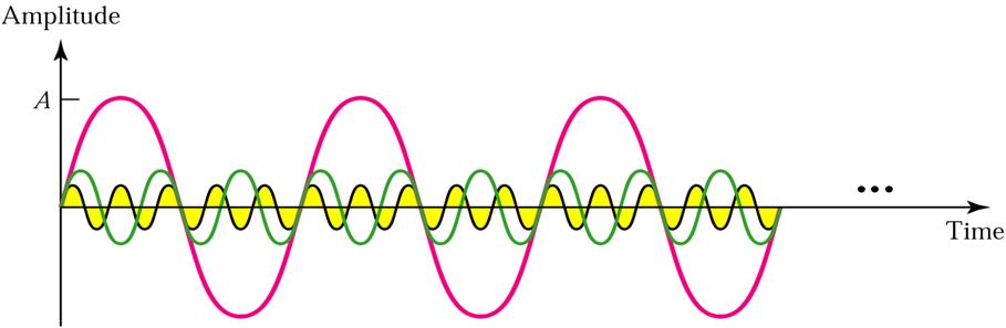
In early 1900s, French Mathematician Jean-Baptiste Fourier showed that any composite signal can be represented as a combination of simple sine waves with different frequencies, phases and amplitudes.
More is the number of components included better is the approximation
For eg., let us consider the square wave …

5. What is a digital signal?
A signal which has discrete values or discontinuous with respect to time.
An analog signal is a signal which varies continuously with respect to time
e.g. i) sinusoidal signal
ii) the output of a microphone when a speaker talks over it
When such signal is transmitted over cable noise gets added to the amplitudes of the signal.
The analog signal may get distorted due to noise and due to non-linear properties of the transmission media.
The signal if distorted cannot be re-constructed even by using amplifiers
Digital Signal
A digital signal is of discontinuous nature in the form of pulses.
The absence of pulse is regarded as zero and its presence as one.
During transmission of such pulses, even if noise gets added up, it will not create a problem.
This is because of the demarking of zero and one with respect to a threshold point.
With digital transmission many techniques like
Data encoding
Data encryption
Data compression
High data rate of transfer
Noise immunity can be obtained


A signal which is continuous with respect to time.
Give examples for analog signal?
Sound, video.


If a signal does not change at all, its frequency is zero.
If it changes instantaneously, its frequency is infinite.
An analog signal is best represented in the frequency domain


An analog signal is best represented in the frequency domain


A single sine wave can carry electric energy from one place to another. For eg., the power company sends a single sine wave with a frequency of say 60Hz to distribute electric energy to our houses.
If a single sine wave was used to convey conversation over the phone, we would always hear just a buzz.
If we sent one sine wave to transfer data, we would always be sending alternating 0’s and 1’s, which does not have any communication value.
If we want to use sine wave for communication, we need to change one or more of its characteristics. For eg., to send 1 bit, we send a maximum amplitude, and to send 0, the minimum amplitude.
When we change one or more characteristics of a single-frequency signal, it becomes a composite signal made up of many frequenies

In early 1900s, French Mathematician Jean-Baptiste Fourier showed that any composite signal can be represented as a combination of simple sine waves with different frequencies, phases and amplitudes.
More is the number of components included better is the approximation
For eg., let us consider the square wave …

The first trace in the above figure is the sum of 2 sine waves with amplitudes chosen to approximate a 3 Hz square wave (time base is msec). One sine wave has a frequency of 3 Hz and the other has a frequency of 9 Hz. The second trace starts with the first but adds a 15 Hz sine wave and a 21 Hz sine wave. It is clearly a better approximation.
5. What is a digital signal?
A signal which has discrete values or discontinuous with respect to time.
An analog signal is a signal which varies continuously with respect to time
e.g. i) sinusoidal signal
ii) the output of a microphone when a speaker talks over it
When such signal is transmitted over cable noise gets added to the amplitudes of the signal.
The analog signal may get distorted due to noise and due to non-linear properties of the transmission media.
The signal if distorted cannot be re-constructed even by using amplifiers
Digital Signal
A digital signal is of discontinuous nature in the form of pulses.
The absence of pulse is regarded as zero and its presence as one.
During transmission of such pulses, even if noise gets added up, it will not create a problem.
This is because of the demarking of zero and one with respect to a threshold point.
With digital transmission many techniques like
Data encoding
Data encryption
Data compression
High data rate of transfer
Noise immunity can be obtained


6. Difference between the analog and Digital signal?

7. Serial and Parallel Communication
SERIAL
Serial communication is the method of transferring one bit at a time
through a medium.
Serial transmission is much more common, particularly over longer distances. It is generally much cheaper as only a single channel between sender and receiver is required, eg: The seven bits (plus one parity check bit) making up an American Standard Code for Information Interchange (ASCII) character are transmitted serially in sequence by the sender and are reassembled into the character by the receiver. A common example of a serial interface
standard is Recommended Standard 232 (RS232).
Three things should be considered when discussing serial communications and the equipment to carry this out:
Electrical standards associated with the interface
Mechanical standards associated with the interface
Standards organisations involved
Data transmission may take place in one direction only or it may be bi-directional. There are 3 groups into which the channel can be classified:
asynchronous transmission:
With asynchronous transmission signal timing is not required; signals are sent in an agreed pattern of bits and if both ends are agreed on the pattern then communication can take place.
Bits are grouped together and consist of both data and control bits. If the signal is not synchronised the receiver will not be able to distinguish when the next group of bits will arrive. To overcome this the data is preceded by a start bit, usually binary 0, the byte is then sent and a stop bit or bits are added to the end. Each byte to be sent now incorporates extra control data. In addition to the control data small gaps are inserted between each chunk to distinguish each group.
In asynchronous transmission each bit remains timed in the usual way. Therefore, at bit level the transmission is still synchronous (timed). However, the asynchronous transmission is applied at byte level, once the receiver realises that there is a chunk of incoming data timing (synchronisation) takes place for the chunk of data.
Asynchronous transmission is relatively slow due to the increased number of bits and gaps. It is a cheap and effective form of serial transmission and is particularly suited for low speed connections such as keyboard and mouse.
One example of asynchronous transfer is Asynchronous Transfer Mode (ATM) switching. ATM allows voice, data and video to be transmitted in fixed length cells of 53 bytes.
PARALLEL
Parallel communication is the method of transferring blocks,
eg: BYTEs, of data at the same time.
Parallel transmission requires a separate channel for each bit to be transmitted. Therefore, to transfer a byte, eight channels will be required between the sender and receiver. Added to these eight are additional channels that are needed for control information and if full duplex communication is required then even more channels would be required. Parallel transmission is rare, other than for very short distances, eg: within a computer, eg: data bus, or between a computer and a printer, eg: Centronics printer interface.
1.6 define channel capacity.
ans:
Transmission Modes
ans:
Simplex

Half Duplex

Full Duplex

Baud and Data Rates


1.7 list different transmission media.
ans:


A twisted pair consists of two insulated wires arranged in a regular spiral mannaer. A wire pair acts as a single communication link

 ans:
ans:
COAXIAL CABLE


It contains cable in a protective cover. it is also like twisted pair that is contains two conductors, but permits a wider range of frequencies.
Data is transmitted through the center wire, while the outer braided layer serves as a line to ground. Both of these conductors are parallel and share the same axis. This is why the wire is called coaxial!


working style for optical fibre
*/


Unguided Media
Light Wave Transmission

Microwave Transmission
ere


Data and Signals
signal:
Electric signals which run through cables are called signals.
A cable is a transmission path and it is also a part of electric circuit, so it needs a positive line and negative line. Therefore, it consists of two conducting wires.
In computer networks, information is communicated through transmission media. Information used in terminals such as computers is digital information, 0 and 1. Because the digital information is sent and received through transmission media, it has to be communicated to a desired terminal in some way.
Signals (electric signals) which run through conducting wires are divided into the following two categories. In addition, a system used when transmitting signals is called a transmission system.

1. Digital signals
Basically, code 1 is transmitted when applying a specific voltage and code 0 is transmitted in the case of 0V.
A system of transmitting digital signals is called baseband system.
2. Analog signals
Signals 0 and 1 are transmitted as electric waves.
A system of transmitting analog signals is called broadband system.
we know that there are two major types of signals are available those are (1) Analog Signal (2) Digital Signal. These two types signals can be transmitted in four possible transmissions.

FAQ'S
SHORT TYPE QUESTIONS
1. d/w analog and digital transmission (oct/nov.2011,08,2010;march/april.09;april/may.2010
2. list the different transmission media. (oct/nov.08,2009)
3. define baud rate and channel capacity. (april/may.2010'oct/nov.2010)
4. explain about infrared and light wave tranmission(march/april.07,oct/nov.2008)
5. state shannoy capacity. (april/may.2012)
6. state the need for data communication networking. (march/april.2009,oct/nov.2009)
7. define half duplex and full duplex. (oct/nov.2009)
8.what is the need of data communication (april/may.2010)
9. briefly explain about serial communication (april/may.2011)
ESSAY TYPE QUESTIONS
1. What is serial and parallel communication. (oct/nov.2008)
2. define Baud rate, simplex, half duplex and full duplex communication. (oct/nov.2009, april/may2011)
3. Explain the cross-sectional view and application of UTP,STP, Coaxial cable and optical fibre. (march/April.2007; (oct/nov.2010)
4. Explain the following:
(a) digital data and digital signals. (april/may. 2011)
(b) digital data and analog signals. (april/may. 2011)
(c) analog data and analog signals.
(d) analog data and digital signals.
5. define the data communications. (Oct/Nov.2011; March/April 09)
6. Explain the shannon capacity and compare the characteristics of various transmission media. (Oct/Nov.2011; March/april-2009)
7. Explain about various transmission media and compare them. (March/April.2009)
8. Explain infrared and light wave transmission.
9. Write two applications of twisted pair, coaxial cable and optical fiber. (April/May. 2010,2011)
10. write two coaxial cable and optical fiber. (April/May. 2010,2011)
11. Explain about the cross section and applications of coaxial cable (April/May.2012)
12. Explain about the cross section and applications of optical fiber. (April/May.2012)


2) wireless keyboard using infrared rays

There are two types of signals that transmits the signals:
1) Analog signal (2) digital signal
Analog
|
Digital
|
1.
It is the form of continuous electrical signal
|
Non continuous
electrical signal
|
2.
Cost of transmission is low
|
High
|
3.
To transmit the data over a long distances, ‘amplifiers’
are used
|
To transmit
the data over a long distances, ‘repeaters’ are used
|
4.
Efficiency is low
|
High
|
5.
Maintenance cost of equipment is high
|
Low
|
6.
Noice is high
|
Noice
is low
|
7.
Analog signals are not easier
and not reliable to transmit
|
Digital signals are easier and more reliable to
transmit with fewer errors.
|
8.
Analog data is slower transmission
when compared to digital
|
Digital data has a faster rate of transmission
when compared to analog, and gives better productivity.
|

7. Serial and Parallel Communication
SERIAL
Serial communication is the method of transferring one bit at a time
through a medium.
Serial transmission is much more common, particularly over longer distances. It is generally much cheaper as only a single channel between sender and receiver is required, eg: The seven bits (plus one parity check bit) making up an American Standard Code for Information Interchange (ASCII) character are transmitted serially in sequence by the sender and are reassembled into the character by the receiver. A common example of a serial interface
standard is Recommended Standard 232 (RS232).
Three things should be considered when discussing serial communications and the equipment to carry this out:
Electrical standards associated with the interface
Mechanical standards associated with the interface
Standards organisations involved
Data transmission may take place in one direction only or it may be bi-directional. There are 3 groups into which the channel can be classified:
asynchronous transmission:
With asynchronous transmission signal timing is not required; signals are sent in an agreed pattern of bits and if both ends are agreed on the pattern then communication can take place.
Bits are grouped together and consist of both data and control bits. If the signal is not synchronised the receiver will not be able to distinguish when the next group of bits will arrive. To overcome this the data is preceded by a start bit, usually binary 0, the byte is then sent and a stop bit or bits are added to the end. Each byte to be sent now incorporates extra control data. In addition to the control data small gaps are inserted between each chunk to distinguish each group.
In asynchronous transmission each bit remains timed in the usual way. Therefore, at bit level the transmission is still synchronous (timed). However, the asynchronous transmission is applied at byte level, once the receiver realises that there is a chunk of incoming data timing (synchronisation) takes place for the chunk of data.
Asynchronous transmission is relatively slow due to the increased number of bits and gaps. It is a cheap and effective form of serial transmission and is particularly suited for low speed connections such as keyboard and mouse.
One example of asynchronous transfer is Asynchronous Transfer Mode (ATM) switching. ATM allows voice, data and video to be transmitted in fixed length cells of 53 bytes.
PARALLEL
Parallel communication is the method of transferring blocks,
eg: BYTEs, of data at the same time.
Parallel transmission requires a separate channel for each bit to be transmitted. Therefore, to transfer a byte, eight channels will be required between the sender and receiver. Added to these eight are additional channels that are needed for control information and if full duplex communication is required then even more channels would be required. Parallel transmission is rare, other than for very short distances, eg: within a computer, eg: data bus, or between a computer and a printer, eg: Centronics printer interface.
1.6 define channel capacity.
ans:
Transmission Modes
ans:
Simplex

Half Duplex

Full Duplex

Baud and Data Rates

Baud Versus Data Rates
Baud rate is the measurement of signal units required to transmit the data. The ideal is to create an efficient system using as few signals as possible. The fewer signals there are, the less bandwidth is required to move data. Baud rate determines that amount of bandwidth required in communications links.
Bit or Data Transmission Rate (DTR) is measured in bits per seconds (bps). The data transmission rate indicates how long it will take to transmit the data, in terms of the user and computer this is the most important information, because DTR is used to compare speeds and performance.
1.7 list different transmission media.
ans:
TRANSMISSION MEDIA
Computers and other telecommunications devices use signals
to represent data. These signals are transmitted from one device to another in
the form of electromagnetic energy. These electromagnetic signals can travel
through air, vacuum or other transmission media. Transmission media can be divided
into two categories
1.
Guided
·
Twisted pairs
·
Coaxial cable
·
Optic fiber cable
2.
Unguided
·
Radio frequency
·
Terrestrial microwave
·
Satellite communication
·
Cellular telephony
The above media depends on the following factors
·
Transmission rate
·
Distances
·
Cost and ease of installation
·
Resistance to environmental condutions
·
bandwidth
Twisted pairs
Cheap cost and most widely used guided transmission medium
is twisted pair.
To reduce crosstalk or electromagnetic
induction between pairs of wires, two insulated copper wires are twisted around
each other. Each connection on twisted pair requires both wires. Since some
telephone sets or desktop locations require multiple connections, twisted pair
is sometimes installed in two or more pairs, all within a single cable
·
These wires commonly used in local telephone
communications and short distance digital data transmission
·
Twisted pairs cable is used for both analog and
digital signals, it is also used in building cabling system
Physical description:


A twisted pair consists of two insulated wires arranged in a regular spiral mannaer. A wire pair acts as a single communication link
Advantages:
·
Least expensive media for short distance transmission
·
Media can be used for both analog and digital
data transmission.
·
Easy maintenance and low installation cost
Disadvantage:
·
Noise signals are easily picked up, it results
is higher error rates.
·
If they are thin cables, breaks easily
·
Limited data rate and limited range
·
Electromagnetic and radio frequency interference
Types of Twisted pairs
1.
Unshielded twisted pair(UTP)
2.
Shielded twisted pair(STP)
Explain about Unshielded twisted pair(UTP)?

Unshielded twisted pair (UTP) is ordinary telephone wire. It
contains a set of pair cable within a plastic case. This is the cheapest
transmission media
It is commonly used for LAN as it is easy to work and
install.
Disadvantages: Which cause to electrical noice and interferences.
Category 5: Defines 100-ohm, four-wire
twisted-pair UTP copper cable that can transmit data at 100 Mbits/sec to
support technologies such as Fast Ethernet and Asynchronous Transfer Mode
(ATM), if installed according to specifications. The cable is low-capacitance
and exhibits low crosstalk. However, all components must be Category 5
compliant; therefore, older modular connectors and jacks are not suitable for
Category 5 installations.
UTP CATEGORIES
Category 1: Unshielded twisted-pair (UTP) cable that is
suited for voice but not data. Most telephone cable installed before 1983 is
Category 1 cable. Not widely used anymore.
Category 2: UTP cable certified for data transmissions up to
4 Mbits/second. Similar to IBM Cabling System Type 3 and is commonly installed
as modern telephone cable. This cable has four twisted pairs.
Category 3: UTP that supports 10-Mbits/sec transmission
rates and is required for token-ring (4 Mbits/sec) and 10-Mbits/sec Ethernet
10Base-T. The cable must have four pairs and three twists per foot.
Category 4: UTP certified for 16 Mbits/sec transmission
rates and is the lowest grade acceptable for 16 Mbits/sec token-ring. The cable
has four pairs.
COAXIAL CABLE


It contains cable in a protective cover. it is also like twisted pair that is contains two conductors, but permits a wider range of frequencies.
Data is transmitted through the center wire, while the outer braided layer serves as a line to ground. Both of these conductors are parallel and share the same axis. This is why the wire is called coaxial!
Just like all electrical components, coaxial cables have a characteristic impedance. This impedance depends on the dialectric material and the radii of each conducting material As shown in this lab, the impedance affects how the cable interacts with other electrical components.
Coaxial cable was invented in 1929 and first used commercially in 1941. AT&T established its first cross-continental coaxial transmission system in 1940.
Coaxial cable was invented in 1929 and first used commercially in 1941. AT&T established its first cross-continental coaxial transmission system in 1940.
- instead of having two wired, coaxial contains a central core conductor of solid dielectrical material
- it can be used over longer distances and support more stations on a shared line than twisted pair.
Applications
- television distribution
- long-distance telephone transmission
- short-run computer system links
- local area network (thernet)
- it is used for cable tv, coaxial cable can carry over 10,000 voice channels simultaneously.
Advantages:
- higher band width
- excellent noce controlling system
- suitable for long distance transmission at higher data tate.
- less cross talk than twisted pair
- used for both analog and digital transmision
disadvantages
- expensive than twisted pair
- less flexible due to thick cable
Optical Fibre cable
In optical fibre technology, lights are used to tranmit
signals instead of electronics. If the light is presence means 1, absence means
0.
Optical fibre is made with glass or plastic and tranmits
signlas in the form of light. The optical fiber cable is composed of core and
classing. A core is surrounded by cladding forming the fibre.
The fiber is covered by a buffer layer that protects it from
moisture, crushing. Finally the entire cable is encased in an outer jacket.


Three components are required for optic fiber:
1). Light source:
it may be LED (light emitting diode) or Laser Diode.
2) Fiber Medium:
which transmits light pulses for which contains particular distance hence there
is no signal losss.
3) Detector: which detects the light and converts it into
electric signals.
Advantages:
1.
provides excellent security.
2.
Optical fibre are noice resistance, less signal
attenuation and higher bandwidth are provided.
3.
Long distance transmission is possible
Disadvantages:
1.
Fiber optic cable is expensive
2.
Difficult to install and repairs are difficult.
3.
Glass fibers are easily breakable than wire.
Cladding: glass
or plastic surrounding the core of an optical fibre; the optical density of the
cladding must be less than of the core.
/* no need to note down just read:working style for optical fibre
For example we would like to pass a flashlight
beam down a long, straight hallway. Just point the beam straight down the
hallway -- light travels in straight lines, so it is no problem. What if the
hallway has a bend in it? You could place a mirror at the bend to reflect the
light beam around the corner. What if the hallway is very winding with multiple
bends? You might line the walls with mirrors and angle the beam so that it
bounces from side-to-side all along the hallway. This is exactly what happens
in an optical fiber.
The light in a fiber-optic cable travels
through the core (hallway) by constantly bouncing from the cladding
(mirror-lined walls), a principle called total internal reflection. Because the cladding does not absorb any
light from the core, the light wave can travel great distances.
However, some of the light signal degrades within the fiber, mostly due to impurities in
the glass. The extent that the signal degrades depends on the purity of the
glass and the wavelength of the transmitted light (for example, 850 nm = 60 to
75 percent/km; 1,300 nm = 50 to 60 percent/km; 1,550 nm is greater than 50
percent/km). Some premium optical fibers show much less signal degradation --
less than 10 percent/km at 1,550 nm.
*/


Unguided Media
Infrared
Transmission
•
Uses
IR signals to transmit data
•
Infrared
have longer wave length than visible light and shorter wave length than radio
waves
•
Infrared
frequencies are higher than microwaves and lower than visible light
•
Used
for short range communication
•
Do
not pass through solid objects
•
Simple
to develop & cost effective
•
Cannot
be used outdoor
•
Low
speed
•
Used
in remote controllers, hand-held devices, laptops etc
•
Modulate non-coherent infrared light
•
Line of sight (or reflection)
•
Blocked by walls
•
IR is used in wireless communications,
monitoring and control applications
e.g. 1. TV remote control
2. IRD port
•
Unguided infra-red waves are widely used in
short range communication like remote controls of TV sets ,stereos , VCRs,
VCDs, DVDs etc
•
They are directional, cheaper and easy to build.
But they don’t pass through solid objects like room walls etc
•
They don’t interfere with similar systems in
adjacent rooms or buildings
Infra-red communication can connect note book
computers, printers and does not require FCC licenseLight Wave Transmission
- it can be used to connect the LAN in two buildings through lasers placed on the top of the roofs
- the optical signals are undirectional and therefore each building must have its own laser and photo dectector
- it offers low cost with very high bandwidth and easy to install.
- it does not require any FCC(Federal communication Commision) license.
- the optical signals are developed by lasers can not pass thorugh thick fog or rain and their directional can be affected by head wavers
Microwave Transmission
ere


signal:
Electric signals which run through cables are called signals.
A cable is a transmission path and it is also a part of electric circuit, so it needs a positive line and negative line. Therefore, it consists of two conducting wires.
In computer networks, information is communicated through transmission media. Information used in terminals such as computers is digital information, 0 and 1. Because the digital information is sent and received through transmission media, it has to be communicated to a desired terminal in some way.
Signals (electric signals) which run through conducting wires are divided into the following two categories. In addition, a system used when transmitting signals is called a transmission system.

1. Digital signals
Basically, code 1 is transmitted when applying a specific voltage and code 0 is transmitted in the case of 0V.
A system of transmitting digital signals is called baseband system.
2. Analog signals
Signals 0 and 1 are transmitted as electric waves.
A system of transmitting analog signals is called broadband system.
we know that there are two major types of signals are available those are (1) Analog Signal (2) Digital Signal. These two types signals can be transmitted in four possible transmissions.
•
Analog signal - Analog transmission
•
Digital signal - Digital transmission
•
Digital signal - Analog transmission
•
Analog signal - Digital transmission
Analog Signal and Analog Transmission
•
Analog signals are continuously varying signals
like human speed signals
•
They can be transmitted as analog signal over
the medium
•
Analog signal suffers from attenuation(Electronics
to reduce the strength, reduction in the strength of a signal.Attenuation occurs with any type of
signal, whether digital or analog)
Attenuation :
Reduction of signal strength during transmission. Attenuation is the opposite of
amplification, and is normal when a signal is sent from one point to another.
•
Amplifiers can be used to improve the gain of
the signals but noise is also amplified
•
The major problem in this type of transmission
is that if a signal gets distorted during transmission it cannot be
reconstructed
•
In human voice transmissions a slight distortion
doesn’t normally matter
•
Therefore, this mode of analog transmission
played a major role in telephony since decades


DIGITAL SIGNAL AND
DIGITAL TRANSMISSION
•
The computer system outputs are in the form of
digital signals
•
A digital signal has infinite bandwidth but
transmission medium has a finite bandwidth
•
The digital signal is also distorted as it
travels along the analog transmission medium
•
The system requires regenerative repeater which
measures signal values at regular intervals and generates them.
•
There is no loss of information but distance
between repeaters is crucial to make the system cost effective.
•
Such a line medium which has repeaters is known
to be a digital line
•
AT & T developed such a digital line called
T1 that carries data at the rate of 1.54 Mbps
Digital Signal and
Analog Transmission


•
The networks are not digital as they don’t have
repeaters on all the lines
•
When the computers were invented and developed,
the telephone network was already in existence in most parts of the world
•
But telephony uses analog signals and analog
circuits
•
Creating a new digital network with repeaters is
very expensive
•
Therefore, analog telephone lines are used to
transmit digital signals
•
This process requires codification technique to
convert digital signal to analog and transmit it over analog telephone channel
with a band width of 4 KHz per channel
•
At the receiving end, the codified signal is
converted back in to digital signal
•
A modem (modulator and demodulator) is used for
this purpose
•
The various codification techniques used are
Amplitude shift keying (ASK), Frequency shift keying (FSK), Phase shift keying
(PSK) and Quadrature amplitude modulation (QAM)
Analog Signal and
Digital Transmission


•
This type of transmission is gaining popularity
due to many reasons like noise immunity, ease of generation etc
•
There are several techniques to achieve this
method, but Pulse Code Modulation (PCM) is most popular
(It could be the transfer of an analog source signal, using an analog modulation method such as Frequency modulation (FM) or Amplitude modulation (AM), or no modulation at all.)
(It could be the transfer of an analog source signal, using an analog modulation method such as Frequency modulation (FM) or Amplitude modulation (AM), or no modulation at all.)
•
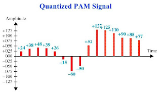
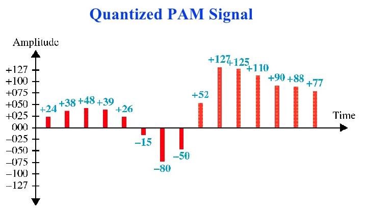
In PCM, the analog signal is sampled at regular
intervals in accordance with sampling theorem at Nyquist rate
•
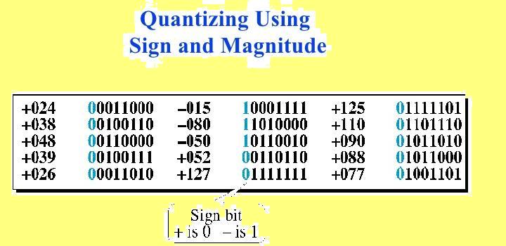
The analog samples are converted in to discrete
signals. The discrete signals are again converted in to binary number with
fixed number of bits
•
The binary number is then transmitted as digital
signal. This process is a form of analog to digital conversion called as
Quantization
•
At the receiving end, digital signal is
converted as binary numbers and separate the discrete signal. Finally, the
original analog signal is reconstructed
•
In order to achieve the above process, the
equipment called CODEC (coder and decoder) is necessary both at transmitting
and the receiving ends
Points:
In this class, you have learnt about
•
Data may be analog or digital
•
Signal may be analog or digital
There are four types of conversions
•
Digital data, digital signal
•
Analog
data, digital signal
•
Digital
data, analog signal
•
Analog
data, analog signal
•
Analog data is continuous values within some
interval
•
e.g. sound, video
•
Digital data is discrete values
•
e.g. text
•
Signals Means by which data are propagated.
•
Digital signals Use two DC components.
•
We can use analog signal to carry digital data
•
Modem
•
We Can use digital signal to carry analog data
Compact Disc audio
Shannon Capacity
Claude Elwood Shannon was the father of electronic communications . He is an American mathematical engineer, whose worked on technical and engineering problems within the communications industry, for both the computer industry and telecommunications. After Shannon noticed the similarity between Boolean algebra and the telephone switching circuits, he applied Boolean algebra to electrical systems at the Massachusetts Institute of technology (MIT) in 1940. Later he joined the staff of Bell Telephone Laboratories in 1942. While working at Bell Laboratories, he formulated a theory explaining the communication of information and worked on the problem of most efficiently transmitting information. The mathematical theory of communication was the climax of Shannon's mathematical and engineering investigations. The concept of entropy was an important feature of Shannon's theory, which he demonstrated to be equivalent to a shortage in the information content (a degree of uncertainty) in a message.
•
In
1944 Shannon gave a formula for channel capacity.
•
Band
width and signal to noise ratio of the channel are taken into consideration.
•
Noise
is white noise only.
•
Shannon's
gave a formula for maximum capacity of data flow through a given bandwidth of a
channel.
shannon took two basic factors: 1) signal-to-noise ratio of the channel (2) Bandwidth
shannon took two basic factors: 1) signal-to-noise ratio of the channel (2) Bandwidth
•
C = B log2 (1+ SNR).
•
where
•
C = Capacity of the channel in bits per sec.
•
B = Bandwidth in Hertz.
•
SNR = Signal-to-Noise ratio in dB.

Signal to noise ratio formula
The signal to noise ratio is the ratio between the wanted signal and the unwanted background noise.
It is more usual to see a signal to noise ratio expressed in a logarithmic basis using decibels:
If all levels are expressed in decibels, then the formula can be simplified to:
The power levels may be expressed in levels such as dBm (decibels relative to a milliwatt, or to some other standard by which the levels can be compared.
•
(SNR)dB = 10 log10 (signal
power/noise power).
Assumptions of Shannon Capacity
theorem
–
The formula assumes White noise (thermal noise).
–
Impulse noise, attenuation distortion or delay
distortion is not accounted for.
–
The wider the bandwidth, the more noise, thus as
B increases, SNR decreases.
–
From formula, capacity increases with Band
width. But Noise also increase with Band width i.e. S/N Ratio decreases.
–
To achieve higher transmission rates, The SNR
should be improved.
Nyquist Bandwidth
•
Nyquist also gave a formula for channel capacity
as
•
C = 2B
log2 M .
Where
–
C = Capacity of the channel.
–
B = Bandwidth.
–
M = Number of discrete signal or voltage levels.
Given the following data, calculate the channel capacity and
deduce number of discrete levels.
–
Spectrum of the channel = 3 to 4 MHz.
–
SNR = 24dB.
–
Then B = 4MHz – 3MHz = 1MHz
SNRdB =
24dB = 10 log10 (SNR)
SNR = 251.
Solution :
–
Using Shannon’s formula,
C = 106
* log2(1+251) =106 * 8 = 8 Mbps
–
Based on Nyquist’s formula
C = 2B log2
M
8 * 106
= 2 * (106) * log2 M
4 = log2
M
No. of discrete
levels M = 16
Calculate the channel transmission rate of ordinary
telephone .
For an
ordinary telephone system,
Channel band width is 300Hz to 3400Hz =3100Hz
SNR = 3162.
Shannon channel
capacity (C) will be
C =
B log2 (1+ SNR)
= 3100 log2 (1+ 3162)
=
3100x 11.62 =36.022 bits/sec
= 36.022 KbpsFAQ'S
SHORT TYPE QUESTIONS
1. d/w analog and digital transmission (oct/nov.2011,08,2010;march/april.09;april/may.2010
2. list the different transmission media. (oct/nov.08,2009)
3. define baud rate and channel capacity. (april/may.2010'oct/nov.2010)
4. explain about infrared and light wave tranmission(march/april.07,oct/nov.2008)
5. state shannoy capacity. (april/may.2012)
6. state the need for data communication networking. (march/april.2009,oct/nov.2009)
7. define half duplex and full duplex. (oct/nov.2009)
8.what is the need of data communication (april/may.2010)
9. briefly explain about serial communication (april/may.2011)
ESSAY TYPE QUESTIONS
1. What is serial and parallel communication. (oct/nov.2008)
2. define Baud rate, simplex, half duplex and full duplex communication. (oct/nov.2009, april/may2011)
3. Explain the cross-sectional view and application of UTP,STP, Coaxial cable and optical fibre. (march/April.2007; (oct/nov.2010)
4. Explain the following:
(a) digital data and digital signals. (april/may. 2011)
(b) digital data and analog signals. (april/may. 2011)
(c) analog data and analog signals.
(d) analog data and digital signals.
5. define the data communications. (Oct/Nov.2011; March/April 09)
6. Explain the shannon capacity and compare the characteristics of various transmission media. (Oct/Nov.2011; March/april-2009)
7. Explain about various transmission media and compare them. (March/April.2009)
8. Explain infrared and light wave transmission.
9. Write two applications of twisted pair, coaxial cable and optical fiber. (April/May. 2010,2011)
10. write two coaxial cable and optical fiber. (April/May. 2010,2011)
11. Explain about the cross section and applications of coaxial cable (April/May.2012)
12. Explain about the cross section and applications of optical fiber. (April/May.2012)
QUIZ
1.
The digital radio system, the channel is
_____________ .
(a) Metallic conductors (b)
Free space (c)
Optical fibre (d)
Coaxial cable
2. ___________ signals are continuous in
nature.
a) analog b) digital c) mixed d) none
3. _______________ play vital role in data communication.
a) Protocols b) Transmission media c)
Both a and b. (d) None
4. Protocols
define _____________ .
a) set of rules b) procedures c) semantics d) all the above
5. Digital signal can be used
to carry analog data .true /false
ans
: true
6. Analog signal can be used to
carry digital data . true/false
ans : true
7. Optical
fibre uses _________ for data
transmission
a)
voltage b)
current c)
light d)
sound
8. Of all the transmission, ________ has the
highest data
transmission rates.
a)
optical fibre b)
Coaxial c)
UTP d)
STP
9. Infrared region lies between _____ and ______
region
a) Microwave,
visible (b) Microwave,
voice (c) Radio
signal, microwave signal
(d) None
of the above
10. Light
cannot penetrate through
a) Rain b) thick fog c) both d) none of the above
11. Shannon considers ________ Noise only for equation.
a) flicker noise b) Gauss noise c)
Shot noise d) White noise
12. This law holds good for
______________ .
a) UTP cable b) STP cable c) Coaxial cable d) All of the
above
13. What is the unit for channel
capacity.
a) words per
second (b) Bits per second (c) Lines per
second (d) All of the
above
14. Shannon's formula depends on
(a) Band width (b) signal to noise
ratio (c) both a & b (d) None of the above
15. the fundamental
basis of data communication is-
(a) light (b) signal propagation (c) voltage
(d) heat
16. ……signals are continuous in nature.
(a) analog (b)
digital (c) mixed (d) none
17. …..signals are on-off in nature.
(a) analog (b) digital
(c) mixed (d) none
18. a…is used to send digital data over analog.
(a) modem
(b) codec (c) multiplexer (d) amplifier
19. A…….is used to represent digital signal in analog form.
(a)
modem (b) codec (c) multiplexer (d) amplifier
20. In…..transmission, all the bits can be transmitted at a
time.
(a) serial (b)parallel. (c) Mixed (d) none
21. ………transmission is generally used for very short
distances.
(a) serial (b)parallel. (c) Mixed (d) none
22. …….transmission is generally used for long distances.
(a) serial (b)parallel (c)mixed (d)none
23. STP helps to eliminate…..
(a)noise (b) error (c)cross
talk (d)voltage
24. The two wires inside a UTP are twisted around each other
to reduce……
(a)noise (b) error (c)cross talk (d)voltage
25. Optical fibre used……for data transmission.
(a) voltage
(b) current (c) light (d) sound
26. Of all the guided media,…has the highest data
transmission rates.
(a) Optical fibre (b)coaxial cable (c) UTP (d) STP
27)Exchange of data takes place between the
a.antenna and receiver
b.modem
c.source and receiver
d.transmitter and antenna
28)What is protocol?
a.it delivers the data
b.delivers the data in time
c.it is a set of rules that controlthe data communication
d.two devices connected together
29)What is the role of OTE in data communication
a.receives the data
b.transmits the data
c.input and output's the data
d.converts the data into another form
30)what is communication considered as when the communicating devices are located near by
a.transmitter
b.remote
c.receiver
d.converter
31)Who is the scientist introduced baud rate
a.J.M.Joseph baud
b.G.J.George baud
c.J.M.George baudot
d.G.J.Carl baud
32)Which is used for very short distance communication
a.microwave
b.infared
c.parallel
d.both b and c
33)In which type of transmission mode synchronization is possible
a.duplex
b.half duplex
c.simplex
d.none
34)Which factor is most needed in data communication network
a.type of transmission
b.type of signals used
c.transmission system utlisation
d.type of signal used
35)Which is a line of sight transmission system
a.infrared
b.microwave
c.parallel transmission
d.both and b
36)Amplitute modulation is used in which type of transmission
a.digital to analog
b.analog to analog
c.none
d.both a and b
37)In mobile communication which transmission is used
a.analog to analog
b.analog to digital
c.digital to analog
d.digital to digital
38)Examples for parallel transmission
a.input to cpu by key board
b.output of printer on a paper
c.both a and b
d.none of the above
39)Does the mesh insulator in co axial cable contains signal
a.yes
b.no
c.-
d.-
40)In fiber optic cable does light intensity is constant all the time
a.yes
b.no
c.-
d.-
41)In transmission system error detection should be done at
a.transmitter
b.receiver
c.both a ans b
d.none of the above.
Note:

latest news on wireless technology
1) Creating Wireless Network Using Visible Light

ScienceDaily (Oct. 6, 2008) — Boston University's College of Engineering is a partner launching a major program, under a National Science Foundation grant, to develop the next generation of wireless communications technology based on visible light instead of radio waves.
2) wireless keyboard using infrared rays

No comments:
Post a Comment