Friday 28 September 2012


.jpg)
Thursday 27 September 2012
Wednesday 26 September 2012
IP ADDRESSING CONCEPTS PPT
What is an IP Address?
What is network prefix and host number?
What is Internet address?
What is sub-netting and no sub-netting?
Monday 24 September 2012
Friday 21 September 2012
Thursday 20 September 2012

csma (Carrier Sense Multiple Access)
What is Carrier Sense Multiple Access


MICRO
PROCESSOR
POLYTECHNIC DIPLOMA PREVIOUS QUESTION PAPERS WITH ANSWERS FOR CPP
POLYTECHNIC
RDBMS PREVIOUS QUESTION PAPERSSaturday 15 September 2012

Step A: Sender creates and sends an email
The originating sender creates an email in their Mail User Agent (MUA) and clicks 'Send'. The MUA is the application the originating sender uses to compose and read email, such as Eudora, Outlook, etc.
Step B: Sender's MDA/MTA routes the email
The sender's MUA transfers the email to a Mail Delivery Agent (MDA). Frequently, the sender's MTA also handles the responsibilities of an MDA. Several of the most common MTAs do this, including sendmail and qmail (which Kavi uses).
The MDA/MTA accepts the email, then routes it to local mailboxes or forwards it if it isn't locally addressed.
In our diagram, an MDA forwards the email to an MTA and it enters the first of a series of "network clouds," labeled as a "Company Network" cloud.
Step C: Network Cloud
An email can encounter a network cloud within a large company or ISP, or the largest network cloud in existence: the Internet. The network cloud may encompass a multitude of mail servers, DNS servers, routers, lions, tigers, bears (wolves!) and other devices and services too numerous to mention. These are prone to be slow when processing an unusually heavy load, temporarily unable to receive an email when taken down for maintenance, and sometimes may not have identified themselves properly to the Internet through the Domain Name System (DNS) so that other MTAs in the network cloud are unable to deliver mail as addressed. These devices may be protected by firewalls, spam filters and malware detection software that may bounce or even delete an email. When an email is deleted by this kind of software, it tends to fail silently, so the sender is given no information about where or when the delivery failure occurred.
Email service providers and other companies that process a large volume of email often have their own, private network clouds. These organizations commonly have multiple mail servers, and route all email through a central gateway server (i.e., mail hub) that redistributes mail to whichever MTA is available. Email on these secondary MTAs must usually wait for the primary MTA (i.e., the designated host for that domain) to become available, at which time the secondary mail server will transfer its messages to the primary MTA.
Step D: Email Queue
The email in the diagram is addressed to someone at another company, so it enters an email queue with other outgoing email messages. If there is a high volume of mail in the queue—either because there are many messages or the messages are unusually large, or both—the message will be delayed in the queue until the MTA processes the messages ahead of it.
Step E: MTA to MTA Transfer
When transferring an email, the sending MTA handles all aspects of mail delivery until the message has been either accepted or rejected by the receiving MTA.
As the email clears the queue, it enters the Internet network cloud, where it is routed along a host-to-host chain of servers. Each MTA in the Internet network cloud needs to "stop and ask directions" from the Domain Name System (DNS) in order to identify the next MTA in the delivery chain. The exact route depends partly on server availability and mostly on which MTA can be found to accept email for the domain specified in the address. Most email takes a path that is dependent on server availability, so a pair of messages originating from the same host and addressed to the same receiving host could take different paths. These days, it's mostly spammers that specify any part of the path, deliberately routing their message through a series of relay servers in an attempt to obscure the true origin of the message.
To find the recipient's IP address and mailbox, the MTA must drill down through the Domain Name System (DNS), which consists of a set of servers distributed across the Internet. Beginning with the root nameservers at the top-level domain (.tld), then domain nameservers that handle requests for domains within that .tld, and eventually to nameservers that know about the local domain.
DNS resolution and transfer process
There are 13 root servers serving the top-level domains (e.g., .org, .com, .edu, .gov, .net, etc.). These root servers refer requests for a given domain to the root name servers that handle requests for that tld. In practice, this step is seldom necessary.
The MTA can bypass this step because it has already knows which domain name servers handle requests for these .tlds. It asks the appropriate DNS server which Mail Exchange (MX) servers have knowledge of the subdomain or local host in the email address. The DNS server responds with an MX record: a prioritized list of MX servers for this domain.
An MX server is really an MTA wearing a different hat, just like a person who holds two jobs with different job titles (or three, if the MTA also handles the responsibilities of an MDA). To the DNS server, the server that accepts messages is an MX server. When is transferring messages, it is called an MTA.
The MTA contacts the MX servers on the MX record in order of priority until it finds the designated host for that address domain.
The sending MTA asks if the host accepts messages for the recipient's username at that domain (i.e., username@domain.tld) and transfers the message.
Step F: Firewalls, Spam and Virus Filters
The transfer process described in the last step is somewhat simplified. An email may be transferred to more than one MTA within a network cloud and is likely to be passed to at least one firewall before it reaches it's destination.
An email encountering a firewall may be tested by spam and virus filters before it is allowed to pass inside the firewall. These filters test to see if the message qualifies as spam or malware. If the message contains malware, the file is usually quarantined and the sender is notified. If the message is identified as spam, it will probably be deleted without notifying the sender.
Spam is difficult to detect because it can assume so many different forms, so spam filters test on a broad set of criteria and tend to misclassify a significant number of messages as spam, particularly messages from mailing lists. When an email from a list or other automated source seems to have vanished somewhere in the network cloud, the culprit is usually a spam filter at the receiver's ISP or company. This explained in greater detail in Virus Scanning and Spam Blocking.
Delivery
In the diagram, the email makes it past the hazards of the spam trap...er...filter, and is accepted for delivery by the receiver's MTA. The MTA calls a local MDA to deliver the mail to the correct mailbox, where it will sit until it is retrieved by the recipient's MUA.
RFCs
Documents that define email standards are called "Request For Comments (RFCs)", and are available on the Internet through the Internet Engineering Task Force (IETF) website. There are many RFCs and they form a somewhat complex, interlocking set of standards, but they are a font of information for anyone interested in gaining a deeper understanding of email.
Email construction and delivery is similar to regular mail by design, because email is modeled on regular mail.
A Message Enclosed in an Envelope
An email message is constructed like a letter you'd send through the postal service: a message enclosed in an envelope. The email envelope header is analogous to the envelope of a hardcopy letter, but some of the information that is ordinarily present on a hardcopy envelope is contained in the message header instead of the envelope header. This header header also contains information that is not usually found on a real-world envelope, but is essential to email delivery and troubleshooting. The envelope header is usually hidden when you view an email, and the message header is usually visible. Together, these two headers are called the full header.
Message Header Fields
Anyone who has used email is familiar with the message header, which is displayed when you view an email message and includes the 'From:', 'To:', 'Cc:', 'Date:' and 'Subject:' fields. The content of these fields differs only slightly from regular mail, because the 'From:', 'To:' and 'Cc:', fields in an email identify the sender and intended recipients by email address.
The Date Field
The message header's 'Date:' field is applied by the originating sender's MUA, so it is only as accurate as the clock on the sender's computer.
The Subject: Field
The 'Subject:' field isn't used in regular mail except in formal business letters where its closest analogy is the 'Re:' line, but this field is necessary for email because without it, you could only differentiate one email from another in the inbox based on the 'From:', 'To:' and 'Date:' fields.
The Return-Path
Email contains more detailed information about its delivery process than the single postmark of regular mail. As the email passes through the delivery chain, MTAs add more interesting and reliable postmark-like timestamps and MTA location information, including the envelope header's 'Received' fields (described in the next section) and the 'Return-Path', which contains the identity of the sender, such as <username@domain.tld>.
The 'Return-Path' is often referred to as the "envelope sender", and this is the address that mailing lists use to determine "who" sent a message. The 'Return-Path' is also the address to which bounces are sent.
The Received field
A 'Received' field added by each MTA in the email delivery chain as it accepts a message for transfer. When a receiving MTA accepts the email for relay or local delivery, it records information about the transaction in the email's envelope header. This includes a message ID that it uses, and which will appear in the MTA server logs, timestamps indicating the time of the transfer and the identity of the sending MTA. If you follow the 'Received' entries in order, they will lead you back to the originating MTA (but not to the senders email address).
This information about the true identity of the sending MTA is valuable when troubleshooting issues with spam or malicious messages. These kinds of messages often contain forged identities in the 'From:' and 'Reply-To' fields, but the true identity of the sending MTA can be extracted from the envelope header. When contacted by the sending MTA, the receiving MTA checks to see whether the hostname provided to it by the originating MTA resolves to a unique IP address. If it does, then it is a fully qualified domain name and the receiving MTA adds the information to the 'Received' field. If the hostname does not resolve properly, the receiving MTA adds the originating MTA's IP address (and possibly also the true hostname) instead.
The Reply-To field
The envelope header also contains a 'Reply-To' address provided by the sender that the receiver can use to reply to the sender. This is analogous to the return address on regular mail. Email messages, particularly automated notifications and messages from mailing lists, often set a different 'Reply-To' address so that bounced messages will be sent to an automated bounce handler. Like a return address on regular mail, the 'Reply-To' address doesn't have to be a real address, but if it isn't, mail sent to it will be undeliverable. Spam and messages containing malware are likely to have false information in the 'From:' and 'Reply-to' fields, but the originator's true Internet address is recorded in the first 'Received' entry in the email's envelope heade
Email and Features


functions of Email
Various Switch Architectures
On completion of this period, you
would be able to know about
•
Network Hub
•
Network Switch
•
Store and Forward switch
•
Cut through switch
•
Adaptive switching mechanism
Network
Hub
•
Hubs, switches, and routers are all devices used to connect one or
more computers to other computers, networked devices, or to other networks
•
Each has two or more
sockets called ports into which one can plug in the cables to make the
connection
•
A hub is typically
the least expensive, least intelligent, and least complicated of the three
•
Hub takes the signal
from one port and sends out to the
other ports after due
amplification and pulse shaping
•
Hub is a physical layer
device
•
Hub is a multi-port
repeater
HUB
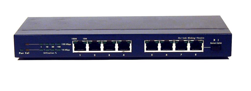

Network Switch
•
A switch does essentially what a hub does but more efficiently
•
Switch also performs
amplification, pulse reshaping functions like hub
•
Switch learns about the
configuration of the network
•
By observing the traffic,
it learns which physical address computer is to which port
•
From the observation it
prepares a forward table
•
When it receives a packet
from a port, it reads the MAC address from the frame header and looks into
forward table. Then forwards the packet only to the port to which the machine with the
destination MAC address is attached
•
Therefore Switch works both
on physical layer and MAC layer
Network Switch

Network Switch

Various Switch Architectures
• Store and Forward
• Cut through
• Adaptive
Store and Forward Switch
• A switch performing store-and-forward will wait to forward a frame until it has received the entire frame
• Store-and-forward is most often used in environments supporting reliable physical or data link protocols
• A received frame is often checked for errors before being forwarded
• This type of switch is inherently slower in environments
• where upper layer protocols already provide reliable
• services
• The tip off that you are dealing with a store and forward
• style switch is whether the switch has buffers
STORE AND FORWARD
Store and forward is a telecommunications technique in which information is sent to an intermediate station where it is kept and sent at a later time to the final destination or to another intermediate station. The intermediate station, or node in a networking context, verifies the integrity of the message before forwarding it. In general, this technique is used in networks with intermittent connectivity, especially in the wilderness or environments requiring high mobility. It may also be preferable in situations when there are long delays in transmission and variable and high error rates, or if a direct, end-to-end connection is not available.
This technique originates the delay-tolerant networks. No real-time services are available for these kinds of networks.
Store and forward networks predate the use of computers. Point-to-point teleprinter equipment was used to send messages which were stored at the receiving end on punched paper tape at a relay center. A human operator at the center removed the message tape from the receiving machine, read the addressing information, and then sent it toward its destination on appropriate outbound point-to-point teleprinter link. If the outbound link was in use, the operator placed the message in tape in a physical queue, usually consisting of a set of clips or hooks. A major relay center in the mid 1900s might have dozens of inbound and outbound teleprinters, scores of operators, and thousands of messages in the queues during peak periods. Operators referred to these centers as "torn-tape relay centers," a reference to removing the received message from the inbound teleprinter by tearing
the paper tape to separate one message from the next. The U.S. military term for such a center
was "Non-Automated Relay Center" (NARC).
Cut Through Switch
• Cut-through switches begin forwarding the frame as soon as the switch has read the destination address
• A cut through switch will forward the data before it has completed receiving the frame
• These switches will function at wire speed, forwarding traffic as fast as it receives it
• Nearly all cut-through switches have no RAM buffers for storing frames
In computer networking, cut-through switching is a method for packet switching systems, wherein the switch starts forwarding a frame (or packet) before the whole frame has been received, normally as soon as the destination address is processed. Compared to store and forward, this technique reduces latency(delaying the time) through the switch, but decreases reliability; corrupted frames are potentially forwarded.
Pure cut-through switching is only possible when the speed of the outgoing interface is equal to the incoming interface speed.
Use in Ethernet
When cut-through switching is used in Ethernet, because the frame check sequence appears at the end of the frame, the switch is not able to verify the integrity of an incoming packet before forwarding it. A cut-through switch will forward corrupted packets, whereas a store and forward switch will drop them.[1]
Fragment free is a variation on cut-through switching that partially addresses this problem by assuring that collision fragments are not forwarded. Fragment free will hold the frame until the first 64 bytes are read from the source to detect a collision before forwarding. This is only useful if there is a chance of a collision on the source port.
Use in ATM
Cut-through switching was one of the important features of IP networks using ATM networks since the edge routers of the ATM network were able to use cell switching through the core of the network with low latency at all points. With higher speed links, this has become less of a problem since packet latency has become much smaller.
Use in InfiniBand
Cut-through switching is very popular in InfiniBand networks, since these are often deployed in environments where latency is a prime concern, such as supercomputer clusters.
-------------------------------------------------------------------------------------------------------------------------------
Adaptive Switch
• Adaptive switch is an advanced switching architecture
• It provides the communications infrastructure with unprecedented high availability, scalability
• It enables Peripheral Component Interconnect (PCI)-based telecommunications, data communications and embedded systems to incorporate 224 PCI bus segments
Adaptive switching dynamically selects between cut-through and store and forward behaviors based on current network conditions
An adaptive switch is designed to operate in cut-through mode (cut-through switching) normally but if a port's error rate jumps too high, the switch automatically reconfigures the port to run in store-and-forward mode
This optimizes the switch's performance by providing higher speed cut-through switching switching if error rates are low but higher throughput store and forward switching if error rates are high.
Adaptive switching is typically done on a port-by-port basis.
In this class, you have learnt about
• Hub is a physical layer device
• Switch is a layer-2 device
• Store and Forward switch stores the entire frame in a buffer then it reads the header then forwards the frame to the concerned port
Cut through switch waits until it receives the frame header, then it forwards the frame to the concerned port without actually waiting for the arrival of the complete frame
Saturday 8 September 2012
Friday 7 September 2012

Thursday 6 September 2012


.jpg)

Tuesday 4 September 2012
Monday 3 September 2012


Sunday 2 September 2012
Packet Switching
Packet Switching
•
Data transmitted in small packets
–
Typically 1000 octets
–
Longer messages split into series of packets
–
Each packet contains a portion of user data plus
some control information
–
Control information
–
Routing (addressing) information
–
Packets are received, stored briefly (buffered)
and passed on to the next node
Store and forward

Switching Technique
•
Station breaks long message into packets
•
Packets sent one at a time to the network
•
The two types of packet switching are:
–
Datagram packet switching
Virtual circuit packet switching
Features of Datagram Packet
Switching
•
Each packet is treated independently
•
Packets can take any practical route
•
Packets may arrive out of order
•
Faster delivery to destination
•
Alternate rooting on node failure
Suitable for short messages


Virtual Circuit Packet Switching
•
Preplanned route established before any packets
sent
•
Call request and call accept packets establish
connection (handshake)
•
Each packet contains a virtual circuit
identifier instead of destination address
•
No routing decisions required for each packet
•
No dedicated path
Virtual circuit packet
switching


Subscribe to:
Posts (Atom)